Optimized fiber optical solutions – product design in every phase
What technologies do we use when working for our customers?
- Manufacturing technology for raw materials, such as tubes, rods, and preforms from ultrapure Fused Silica
- Fiber drawing technology for standard optical fibers and special optical fibers, capillaries, and tapers made from Fused Silica or optical glass (special applications)
- Coating technology for optical fibers with acrylate, silicone, polyimide, and low-refractive coating materials
- Extrusion technology for optical fibers with polyamide or ETFE
- Planar waveguide technology for optical splitters
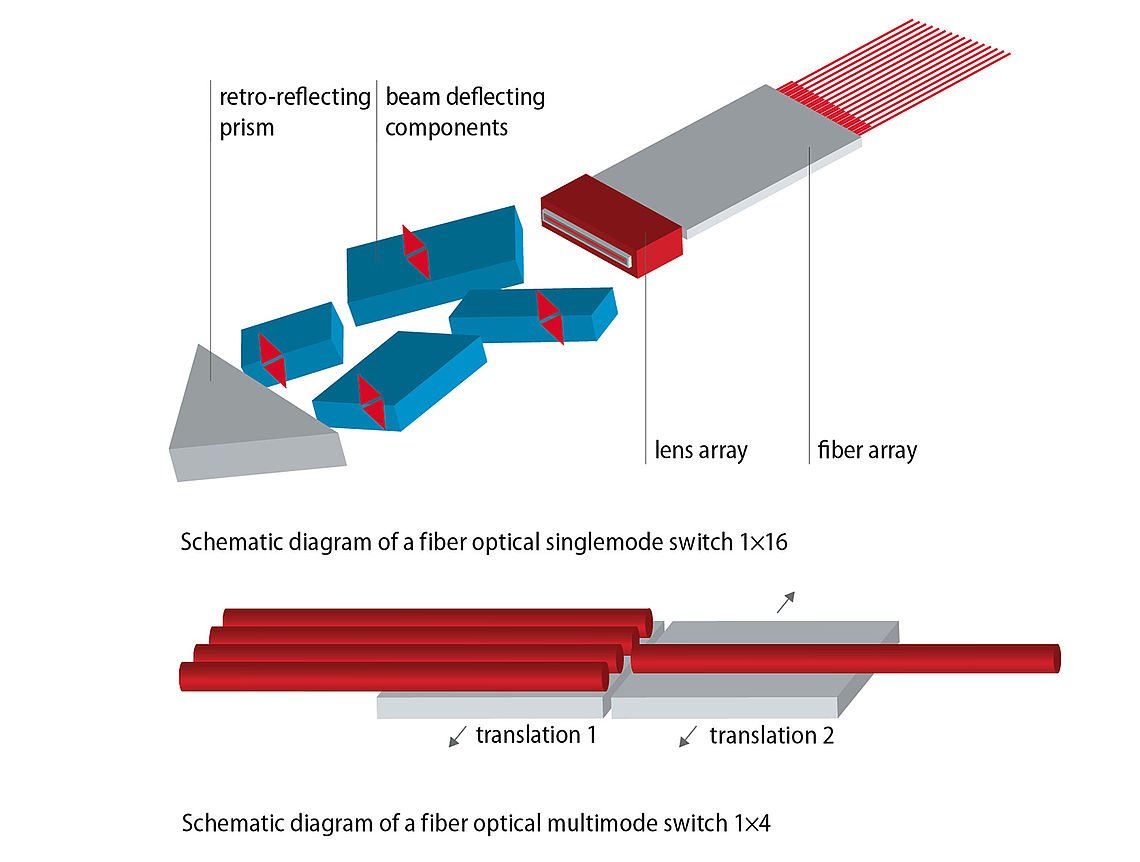
- Micro-optical/micro-mechanical technology for fiber optical switches
- Assembly technology for silica optical fibers, glass fibers, polymer fibers, plastic-coated fibers, and fiber bundles
- Assembly technology for optical laser probes used in patient-centered medicine (according to German Medical Devices Act, MPG)
- Manufacturing technology for spectroscopic probes and fiber arrays
Manufacturing technology for raw materials, such as tubes, rods, and preforms from ultrapure Fused Silica
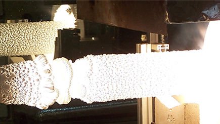
Molten glass
Synthetic Fused Silica is created as an ultrapure silicon compound from the chemical reaction in the vapor phase. This manufacturing technique guarantees the very highest purity and therefore the lowest optical absorption.
The process for creating Fused Silica developed by the Jena Glaswerk is characterized by the flame hydrolysis decomposition of the synthetic silicon tetrachloride – an ultrapure, colorless, aggressive, and highly humidity-sensitive fluid. During hydrolytic decomposition in a hydrogen/oxygen flame, minute (50 nm) particles of silicon dioxide are created, which fuse into ultrapure Fused Silica cylinders due to the extreme temperature of this flame (> 2700 K).
SiCl4 + 2 H2 + O2 -> SiO2 + 4 HCl

Since Fused Silica itself exhibits high viscosity at high temperatures, and to avoid contamination by fireproof materials, a technique without a crucible is used to deposit the SiO₂ particles onto the front face of a slowly rotating attachment. This attachment, which is made from natural quartz, is clamped in the carriages of a lathe and is moved away from the burner at a velocity that matches the fusing speed. This kind of fusing facility also includes a gas volume controller for the burner gases, a raw material feed unit (the liquid SiCl₄ is vaporized in carefully controlled quantities), the PLC-driven plant control system, and the waste gas extractor. The waste gas produced by this process is extracted for separation and neutralization in a waste gas scrubbing plant.
The production process, from igniting the multi-nozzle Fused Silica burners developed in-house to achieving maximum ingot mass, lasts several days. Production in the melt kilns runs in parallel, and this process and its parameters are monitored continuously by operating personnel.
POVD manufacturing process
The fluorine-doped step-index (FSI) preforms are manufactured by using a plasma-based coating process. Manufacturing a preform is a multi-stage production process in which the quality of the Fused Silica and the capabilities of the manufacturing technology itself are both decisive. We manufacture a wide variety of preforms either for further processing in-house or for OEM customers.
Ultrapure Fused Silica rods are cladded with fluorine-doped silica layers to give the preform its required step-index profile. To achieve this, we use a high-frequency plasma heat source to trigger the chemical reaction between SiCl₄, oxygen, and a fluorine-rich gas. The plasma’s high temperature produces the coating conditions that guarantee a very high concentration of fluorine in the cladding material.

Fiber drawing technology for standard optical fibers and special optical fibers, capillaries, and tapers made from Fused Silica or optical glass (special applications)
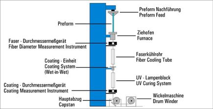
The completed preform is prepared for the drawing process in our in-house draw towers. This involves the preform being secured to the top of the tower and then heated in a kiln to over 2,000 °C. The drawing process starts with a silica droplet. This is followed by a continuous, ultrapure fiber a few micrometers thick, which cools as it descends. To protect the silica fiber, it is given a dual-layer acrylate coating during drawing. This ensures the fiber is protected against environmental factors and can now be processed into any kind of cable. The fiber has now achieved its characteristic diameter of 0.25 mm (or alternatively 0.5 mm). Once wound onto reels, the fiber is then sent on to quality control.

Coating technology for optical fibers with acrylate, silicone, polyimide, and low-refractive coating materials
To protect the fibers against environmental factors, they are clad with appropriate materials during the drawing process. Depending on the application scenario, the various benefits conferred by the coating properties of acrylate, silicone, or polyimide can be utilized. Low-refractive coating materials are used in order to improve the bending properties of the fibers.
Extrusion technology for optical fibers with polyamide or ETFE
After the first coating, a further protective layer may be needed, depending on the application. This is applied in a separate extrusion process. Polyamide or ETFE is typically used here, although other materials are conceivable.
Planar waveguide technology for optical splitters
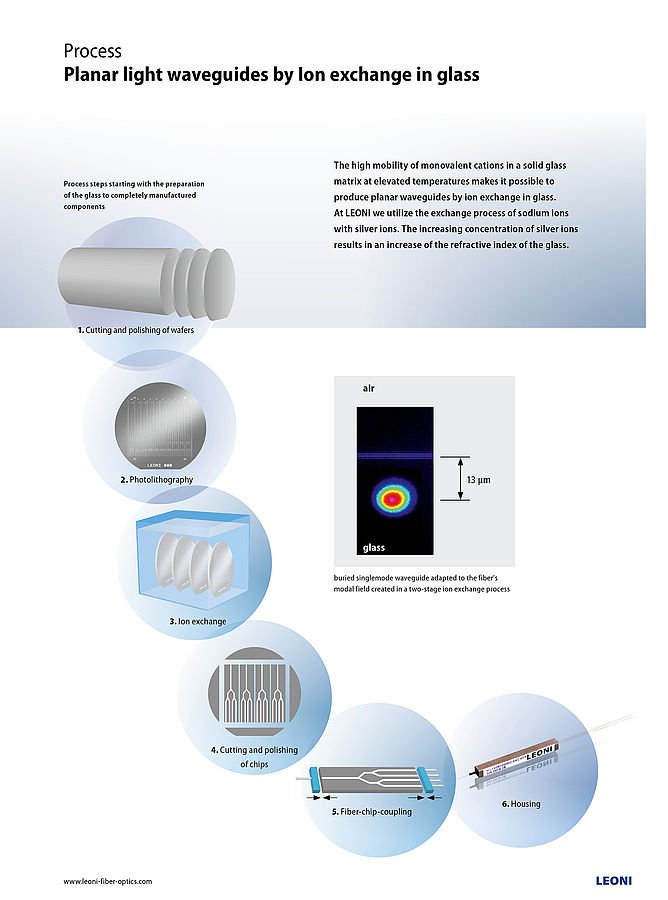
Our splitter manufacturing is based on a planar waveguide technology. The planar lightwave circuits (PLC) are developed and produced using a lithographic procedure. Our planar-integrated multimode splitters are also manufactured using ion exchange in glass. This makes them highly compact, rugged, and durable.
Micro-optical/micro-mechanical technology for fiber optical switches
Assembly technology for silica optical fibers, glass fibers, polymer fibers, plastic-coated fibers, and fiber bundles
- Centering and joining (bonding, clamping) of various fiber types in various connector and connection systems (standard, special, and customer-specific connection systems, e.g. for high-power laser beam guiding systems)
- Finish end faces and polish with an ultrafine grain
- Final inspection
- Customer-specific mixing or mapping of individual fibers in fiber bundles
Assembly technology for optical laser probes used in patient-centered medicine (according to German Medical Devices Act, MPG)
- Assembly technology similar to optical fibers, but usage of biocompatible fibers according to German Medical Devices Act/FDA, etc. as regards the clean room manufacturing process, safety, and documentation
- In clean rooms, the distal tips of the fiber ends are processed in order to meet the requirements of the respective medical application -> distal tip design
- Standard and customer-specific connector systems are affixed to the proximal tip (using bonding, clamping)
Manufacturing technology for spectroscopic probes and fiber arrays
- Processing of multiple fibers in lines, plug connections to opposing side (cross-section conversion from round to square)
- Combiners (fiber-based splitters, non-planar; many fibers to one connector)
- Arrays: linear fiber configurations, 1- or 2-dimensional, customer-specific, asymmetric possible
-
A coordinated probe design for special optical fibers to protect against the environmental conditions in your specific application:
- probe heads for optical measurements with specific equipment for your measurement scenario (e.g. window, integrated air purging, high-temperature)
- Incl. electronics by customer request
Contact
Please contact us for further information. We look forward to your inquiry.
Europe, Africa, and Asia (excl. China)
Phone +49 36764-81-100
Email sales-europe@weinert-industries.com
China
Phone +86
519-8988-7783
Email sales-china@weinert-industries.com
North and South America
Phone +1
757-258-4805
Email sales-americas@weinert-industries.com


